|
So, just how does one
calculate dihedral
angles? With correct signs?
This may sound like a trivial
task to
some. And, calculating the angle itself is really quite simple. But,
when it comes to figuring out the sign it's another story. Especially
if you're trying to automate the calculation instead of eyeball every
Newman projection. If you find this really useful, it's taken from my
Ph.D. thesis. (It can be referenced as J.K. Rainey, Ph.D. Thesis,
University of Toronto, 2003. In case you're interested, the thesis
title is "Collagen structure and preferential assembly explored by
parallel microscopy and bioinformatics." All of this work was under the
supervision of Prof. M. Cynthia Goh.) The procedure here is based upon
the description of IUPAC specifications for dihedral angles. This can
be found in a paper published in a variety of journals (e.g. JMB, J Biomol
NMR) circa
1998, authored by Markley et
al. and
titled Recommendations
for the presentation of NMR structures of proteins and nucleic acids.
First, which dihedrals are we
typically
concerned with? How about some
Newman projections to make that perfectly clear:
So, we have the three
standard
dihedral angles, ϕ, Ψ, and ω, that specify backbone
conformation and
the first of several angles, χ1,
specifying our side-chain
conformation. This all follows from pioneering work by
Ramachandran and co-workers - the widely used Ramachandran plot showsϕ vs. Ψ.
For each of the dihedral angles, we need four atoms in order to specify
it exactly. Using the above Newman projections, these can be readily
seen along with the following generic Newman projection:
In the following math, these
generic atom names will be used. Just plug in coordinates for the
appropriate atoms. Note that a clockwise rotation
(<180°) for F1 to eclipse B1
will be a positive dihedral, by convention.
Okay, now
onto the
math.
To determine a dihedral
angle θ between two bonds F1-Fc
and B1-Bc about
a common bond Fc-Bc, where Fc is the
front atom and Bc
the back atom in
a Newman projection (Figure above), two planes are first defined:
The points Fc
and Bc
are common to both
planes; for each plane, then, the parametric equation of the plane in
form Ax + By + Cz = D is given by
(Bc-Fc)
x (F1-Fc)
= nF
(1)
(Fc-Bc) x (B1-Bc)
= nB
where the components of
(vector) nF
are equivalent to [A,B,C] for the plane
containing F1, Fc and Bc
and likewise
for nB; values of D are
not
calculated, since they are not needed in the subsequent analysis. (Thanks to Steen Christensen
of the
Technical University of Denmark for pointing out that the common bond
vectors were reversed in direction!) The
following three conditions must be met for a unit vector in a given
plane, ûF or ûB respectively, that
is also
perpendicular to
Fc-Bc:
û
·
Fc-Bc = xûxc
+ yûyc +
zûzc = 0
(2)
A xû
+ B yû
+ C zû = D
(3)
xû2
+ yû2 + zû2 = 1
(4)
where these equations are
applicable to either plane. In graphical terms, these unit vectors
appear as something like:
To simplify the
algebra, the planes are translated to pass through the origin
by
translating the atom Fc exactly to the origin,
and
translating the
other three atoms with the same transformation:
Fc’
= Fc - Fc = [0, 0,
0]
(5)
F1’
= F1
- Fc
Bc’
= Bc
- Fc
B1’
= B1
- Fc
This makes D = 0 for eq.
3 while
retaining the relative locations of
each atom. (Therefore, it is irrelevant whether eq. 1 is carried out
before or after translation by eq. 5.) Solving the three eqs. 2
to 4 for the components of û gives:
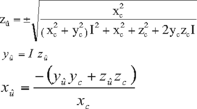 (6)
(6)
where I is given by:
I = (A zc/xc - C)
/ (B - A yc/xc)
(7)
and (xc,
yc, zc)
represents the
component form of the vector Fc-Bc; as long as this is
carried out
after transformation by eq. 5, the simplification that D=0 will be
valid. Note that eq. 6 has two roots. In order to ensure that the
appropriate û is in the direction of F1
or B1,
as in the above figure illustrating ûF and ûB, the desired unit vector
is that
set of coordinates which forms a
smaller angle of form ûF-Fc-F1
or ûB-Bc-B1,
respectively.
The magnitude of the dihedral angle illustrated is then given by the
angle between the two unit vectors,
ûF and ûB. For the less
geometrically
inclined, a nice simple way to calculate this is:
arccos({ûF · ûB} / { ||ûF|| ||ûB|| }
)
(8)
which simplifies very
nicely since
both are unit vectors, and are therefore length (= norm symbol ||x||)
1, to
arccos(
ûF · ûB) = arccos(xûxû
+ yûyû +
zûzû)
(9)
Finally, the sign of the
dihedral
angle must be determined:
Thanks
to Dr. John W. Logan from Stanford for alerting me to the following
method for sign calculation which answers my plea of "there must be a
simpler way to do this"! (My original method employing rotation
matrices is given below - but, the much more efficient method employs a
single dot product.) This is based on an article by Bekker et al. in J.
Comp. Chem. 16: 527 (1995), which forms Chapter
5 of H.
Bekker's Ph.D. Dissteration available at RUG.
Note that the above
calculation is all based on a cross-product definition;
a dot-product definition may also be derived - Dr. Logan tested this
out and found it to be computationally
slower than the cross-product definition. (See again Bekker's work for
a comparison of the two definitions.)
If we consider the following projection looking down the bond Fc->Bc

we can make use of the angle α between nB and
bond vector (Fc-F1).
As you can see from the above diagram, any dihedral angle with a
negative sign (as the shown angle is) will have angle α with a magnitude greater
than
90°. Conversely, once bond vector (Bc-B1)
goes into the region of the plane shown above where it implies a
postive dihedral, α will have a magnitude
less than 90°. So, this means
that we can
go ahead and exploit the dot product: a dot product between nB
and bond vector
(Fc-F1) will be positive
when |α| < 90° &
negative when 90° < |α| <= 180°. So, you can
get the sign of
the dihedral by:
sign = sign(nB·(Fc-F1))
Note: Although I haven't personally tested the above sign expression
yet, David Lomelin
from
UCSF tells me that it indeed works. He was also nice enough to send the
following correction: the criteria should be <= 180° (as now
listed), rather than
just < 180° as was
originally listed!
For posterity: the rotation
matrix
method.
Unfortunately (from the
simplicity
standpoint), the way that I came up with to do this determination
consistently time after time requires a series of rotations. Here, the
goal is to rotate Fc-Bc such that
it is parallel to an axis; this allows direct comparison of the
relative angles of each of the û vectors. First a rotation
about
z is
carried out to bring Fc-Bc into the xy-plane
using
 (10)
(10)
with
θ1
= - α = - arctan
(yc /
xc)
(11)
with the constraint that θ1 in this case is
determined such
that
rotation is carried out to the nearest z axis (i.e., if 180° > |α| >
90° then α = - (180°
- α)
with the
necessary 360°
subtraction if
(180° - α)
> 180°.) This rotation,
and the subsequent one, are applied to Fc-Bc, ûF, and ûB. Second, the three
vectors are
rotated about the
y-axis
 (12)
(12)
to bring the rotated Fc-Bc to the x-axis; here the
angle between (Fc-Bc)’ and the
positive x-axis is given
by
θ2
= arctan (
[zc]’ / [xc]’
).
(13)
Note: I use one ' to
represent a
vector or vector component with one rotation carried out or '' for the
doubly rotated version. Each of the vectors ûF'' and ûB'' now have
components only in the yz-plane since they were both defined as
perpendicular to the Fc-Bc vector. The (relative)
angle
assumed by each
is given by
θû = arctan ( [yû]’’
/ [zû]’’
)
(14)
for each vector.
Comparison of the
angle of rotation of ûF'' to ûB'' then readily provides
the sign of
the dihedral angle.
Specifically, if ûF'' is rotated clockwise
relative to ûB'' by
less than 180° (as is the case
illustrated in
last of the Figures above) the
dihedral angle will be positive; conversely, a counterclockwise
rotation in such a relative frame is negative. Note that if (Fc-Bc)’’
lies along the -x-axis instead of the +x-axis the rotations will be
reversed.
So, that's my method to
calculate
and assign correct signs to dihedral angles. This worked consistently
for a dataset of somewhere in the ballpark of 180,000 residues, so I'm
quite sure it is reliable. There may very well be a simpler way to do
this, but I couldn't think of one or find one discussed. Please let
me know if you have issues with this etc.,
find mistakes (this is transcribed from my thesis, which is
transcribed from the original pencil and paper derivation - I've
checked it fairly closely, though), or know of some super simple way to
do the same thing!
Last updated: June 2, 2005.
|